Dense-phase CO₂ pipelines operate in a thermodynamic region where small variations in pressure and temperature produce disproportionately large changes in fluid properties. Conventional FEED tools simplify this behavior, leading to design errors when pipelines encounter temperature swings, elevation changes, startups, or shutdowns. This case study demonstrates how the Vanmok CO₂ Simulator was used to evaluate an industry-scale pipeline and determine the correct number and placement of compressor/booster stations based on thermodynamics and transient behavior.
The Problem with Conventional CO₂ Pipeline Modeling
Most pipeline simulation tools were developed for subcritical gas and liquid regimes. They fail to capture the sharp property variations near the critical point where CO₂ pipelines operate. These simplifications introduce property estimation errors of 10–30%, which propagate into FEED hydraulic studies, compressor station sizing, and transient modeling.
Why This Matters in Practice
Real pipelines experience temperature swings, elevation changes, and transient regimes during startup and shutdown. Steady-state FEED calculations do not capture the density and pressure envelope changes caused by these conditions.
Simulator – A Different Approach
The Vanmok CO₂ Simulator uses explicit, regularized thermodynamic correlations for CO₂ near the critical region. The model provides numerically stable transient simulation across gas, liquid, critical, and supercritical regimes and functions as a digital twin supporting both FEED and operational analyses.
Case Study Scenario
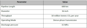
 |
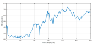 |
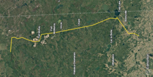
| Figure 1. Pipeline Right of Way | Figure 2. Elevation profile of pipeline |
Conventional FEED Approach
Traditional FEED studies assume average density and friction factors, while neglecting near-critical sensitivity, temperature effects, elevation impacts, and transient regimes. This often leads to incorrect compressor station counts.
What the Vanmok CO₂ Simulator Evaluated
The simulator evaluated pressure–density sensitivity, seasonal temperature profiles, elevation-driven hydrostatic effects, startup and shutdown transients, and minimum pressure envelopes required to avoid phase changes.
Simulator Findings
Vanmok CO₂ Simulator identified the need for three stations to prevent two-phase formation during transient and cold operating conditions.
Recommended configuration:
– 1 inlet compressor station at inlet with discharge pressure of 15 MPa
– Booster stations at approximately 215 km and 330 km
Figure 1 shows the phases along the pipeline length with no booster, middle booster and two boosters. Simulator predicted vapor and liquid phases with no booster, liquid phase still existed with a middle booster, and completely eliminated liquid and vapor phases with two boosters.
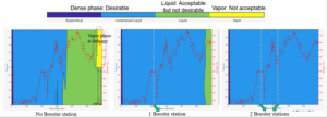
(a) (b) (c)
Figure 1. Visualization of phases along the pipeline length showing vapor and liquid phases with (a) no booster, (b) liquid phase still exist with a middle booster, and (c) elimination of liquid+vapor with two boosters.
Critical Engineering Insight
The requirement for additional stations was driven by near-critical thermodynamics and transient behavior, not friction losses.
Value Delivered
Using the Vanmok CO₂ Simulator during FEED prevented under-design, avoided over-design, and provided defensible station spacing based on physics across all operating modes.
Conclusion
For dense-phase CO₂ pipelines, compressor station count is fundamentally a thermodynamic problem. Vanmok CO₂ Simulator facilitates informed and accurate design decisions during the pre-construction phase.
Click Here to Select What if Scenarios for your CO2 Pipeline During FEED Stage Studies
Contact Vanmok
www.vanmokld.com
info@vanmok.com